Blutooth Controlled Rover Robot

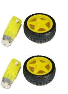
BO DC Motor and wheels set

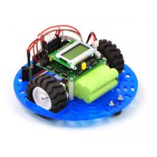
This is my first post and i hope you all will like it.this robot i have built several times for Engineering and science college final year students here in India.
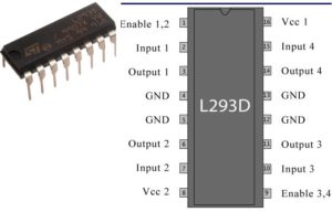
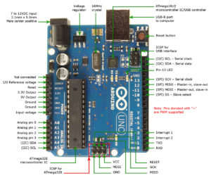
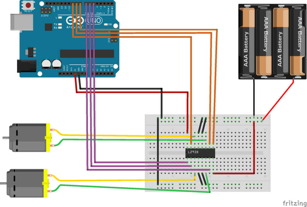
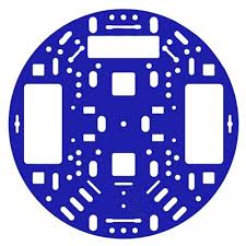
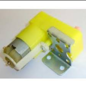
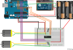
The Above Pics show the list of components needed and the schematics of how to connect Arduino Uno to l293d motor controller chip.
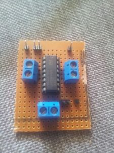
One thing to specify here is one needs to have basic knowledge in electronics to complete this robot or one should take guidance from one who understands electronics.
Once you built the robot and built the complete controller electronics according to the schematics or the circuit diagram image i have shown above ,interface your bot with PC or your laptop make sure it has Arduino IDE software installed on it or download and install it from Arduino.cc website for free.
Open Arduino IDE on your PC and click open new sketch for file menu.
in new sketch delete everything present in the sketch and copy and paste following code.make sure that you have selected proper serial port for Arduino detected in device manager in windows.also make sure Arduino Uno is selected under boards menu under Tools menu.
verify and upload code by clicking necessary arduino IDE buttons.
wait till code is loaded and if everything is fine than robot should start working.
This code is only for testing robot motors the Bluetooth control code has to be blended with the present code later if basic robot is working.
—————— copy CODE from Below this line ———————-
/*
L293 based basic Robot Control code.This code is for testing the basic functionality i.e whether motors are working using arduino software control .
This example code is in the public domain.
*/
// Pin 13 has an LED connected on most Arduino boards.
// give it a name:
int enableA = 5; ///pin6 of l293
int input1 = 6; ///pin5 of l293
int input2 = 7; ///pin7 of l293
int enableB = 9; ///pin11 of l293
int input3 = 10; ///pin10 of l293
int input4 = 15; ///pin12 of l293
// the setup routine runs once when you press reset:
void setup() {
// initialize the digital pin as an output.
pinMode(enableA, OUTPUT);
pinMode(enableB, OUTPUT);
pinMode(input1, OUTPUT);
pinMode(input2, OUTPUT);
pinMode(input3, OUTPUT);
pinMode(input4, OUTPUT);
}
// the loop routine runs over and over again forever:
void loop()
{
forward();
}
int reverse(){
digitalWrite(input1,LOW ); // turn the LED on (HIGH is the voltage level)
digitalWrite(input2,HIGH); // turn the LED off by making the voltage LOW
digitalWrite(input3, HIGH); // turn the LED on (HIGH is the voltage level)
digitalWrite(input4, LOW); // turn the LED off by making the voltage LOW
digitalWrite(enableA, HIGH); // turn the LED on (HIGH is the voltage level)
digitalWrite(enableB, HIGH); // tur
}
int forward(){
digitalWrite(input1,HIGH ); // turn the LED on (HIGH is the voltage level)
digitalWrite(input2,LOW); // turn the LED off by making the voltage LOW
digitalWrite(input3,LOW ); // turn the LED on (HIGH is the voltage level)
digitalWrite(input4,HIGH ); // turn the LED off by making the voltage LOW
digitalWrite(enableA, HIGH); // turn the LED on (HIGH is the voltage level)
digitalWrite(enableB, HIGH); // turn the LED off by making the voltage LOW
}
int turnright(){
digitalWrite(input1,LOW ); // turn the LED on (HIGH is the voltage level)
digitalWrite(input2,HIGH); // turn the LED off by making the voltage LOW
digitalWrite(input3,LOW ); // turn the LED on (HIGH is the voltage level)
//
digitalWrite(input4,HIGH ); // turn the LED off by making the voltage LOW
digitalWrite(enableA, HIGH); // turn the LED on (HIGH is the voltage level)
digitalWrite(enableB, HIGH); // turn the LED off by making the voltage LOW
}
int turnleft()
{
digitalWrite(input1,HIGH ); // turn the LED on (HIGH is the voltage level)
digitalWrite(input2,LOW); // turn the LED off by making the voltage LOW
digitalWrite(input3,HIGH ); // turn the LED on (HIGH is the voltage level)
digitalWrite(input4,LOW ); // turn the LED off by making the voltage LOW
digitalWrite(enableA, HIGH); // turn the LED on (HIGH is the voltage level)
digitalWrite(enableB, HIGH); // turn the LED off by making the voltage LOW
}
—————— copy CODE from above this line ———————-
This robot is controlled using freely available Arduino Apps for Android phone available on Google Play.
kindly go through following page and down this app for free on you android or tab which will allow you to control your bot using android phone.
The page through the courtesy of Hobbyprojects.com
has following instructions kindly go through them they are very easy to understand.they are as follows:
App Instructions:
1. First make sure your HC-05 Bluetooth Module is paired with your mobile. The default password for pairing is “1234” or “0000”. Check the manual of Bluetooth module.
2. Click on “SELECT DEVICE” icon to select paired Bluetooth module.
3. When you press “UP Arrow” it sends the data “A” to Bluetooth Module connected with the circuit. When Microcontroller detects “A” the Robot / Robot Car moves FORWARD.
4. When you press “Down Arrow” it sends the data “B” to Bluetooth Module connected with the circuit. When Microcontroller detects “B” the Robot / Robot Car moves REVERSE.
5. When you press “LEFT Arrow” it sends the data “C” to Bluetooth Module connected with the circuit. When Microcontroller detects “C” the Robot / Robot Car turns LEFT.
6. When you press “RIGHT Arrow” it sends the data “D” to Bluetooth Module connected with the circuit. When Microcontroller detects “D” the Robot / Robot Car turns RIGHT.
7. When you press “STOP” button which is in the center of remote it sends the data “E” to Bluetooth Module connected with the circuit. When Microcontroller detects “E” the Robot / Robot Car gets STOPPED.
8. When you press “360 Degree” button it sends the data “F” to Bluetooth Module connected with the circuit. When Microcontroller detects “F” the Robot / Robot Car rotates CLOCKWISE on the same position.
9. When you press “-360 Degree” button it sends the data “G” to Bluetooth Module connected with the circuit. When Microcontroller detects “G” the Robot / Robot Car rotates ANTI-CLOCKWISE on the same position.
10. Click on “DISCONNECT” icon to disconnect paired Bluetooth module.
Now i will consider that your basic robot without bluetooth is working fine, that means wheels of robot are rotating in one direction.
now go through the below image and wire your Bluetooth Module to the robot.
Once Bluetooth has been wired sucessfully kindly upload the complete code given below.
—————— copy CODE from below this line ———————-
/*Thia cod is for L293Chip
This is basic obstacle avoidance reverse forward rover robot code by Danuc Robotics India
works great
This example code is in the public domain.
*/
#include <SoftwareSerial.h>// import the serial library
SoftwareSerial tron(2, 3); // RX, TX
int ledpin=7; // led on D13 will show blink on / off
int BluetoothData; // the data given from Computer
// Pin 13 has an LED connected on most Arduino boards.
// give it a name:
int sensorPin = A5; // select the input pin for the potentiometer
int ledPin = 13; // select the pin for the LED
int sensorValue = 0; // variable to store the value coming from the sensor
int enableA = 5; ///pin6 of l293
int input1 = 6; ///pin5 of l293
int input2 = 7; ///pin7 of l293
int enableB = 9; ///pin11 of l293
int input3 = 10; ///pin10 of l293
int input4 = 15; ///pin12 of l293
// the setup routine runs once when you press reset:
void setup() {
Serial.begin(9600);
// put your setup code here, to run once:
tron.begin(9600);
Serial.begin(9600);
Serial.println(“Danuc Robotics Bluetooth control”);
pinMode(ledpin,OUTPUT);
// initialize the digital pin as an output.
digitalWrite(enableA, HIGH); // turn the LED on (HIGH is the voltage level)
digitalWrite(enableB, HIGH); // turn the LED off by making the voltage LOW
pinMode(enableA, OUTPUT);
pinMode(enableB, OUTPUT);
pinMode(input1, OUTPUT);
pinMode(input2, OUTPUT);
pinMode(input3, OUTPUT);
pinMode(input4, OUTPUT);
}
// the loop routine runs over and over again forever:
void loop()
{
if (tron.available()){
BluetoothData=tron.read();
Serial.println(BluetoothData);
}
delay(1); // delay in between reads for stability
if(BluetoothData==’A’)
{
reverse();
}
else if(BluetoothData==’B’)
{
forward();
}
else if(BluetoothData==’C’)
{
turnleft();
}
else if(BluetoothData==’D’)
{
turnright();
}
}
int reverse(){
digitalWrite(input1,LOW ); // turn the LED on (HIGH is the voltage level)
digitalWrite(input2,HIGH); // turn the LED off by making the voltage LOW
digitalWrite(input3, HIGH); // turn the LED on (HIGH is the voltage level)
digitalWrite(input4, LOW); // turn the LED off by making the voltage LOW
digitalWrite(enableA, HIGH); // turn the LED on (HIGH is the voltage level)
digitalWrite(enableB, HIGH); // tur
}
int forward(){
digitalWrite(input1,HIGH ); // turn the LED on (HIGH is the voltage level)
digitalWrite(input2,LOW); // turn the LED off by making the voltage LOW
digitalWrite(input3,LOW ); // turn the LED on (HIGH is the voltage level)
digitalWrite(input4,HIGH ); // turn the LED off by making the voltage LOW
digitalWrite(enableA, HIGH); // turn the LED on (HIGH is the voltage level)
digitalWrite(enableB, HIGH); // turn the LED off by making the voltage LOW
}
int turnright(){
digitalWrite(input1,LOW ); // turn the LED on (HIGH is the voltage level)
digitalWrite(input2,HIGH); // turn the LED off by making the voltage LOW
digitalWrite(input3,LOW ); // turn the LED on (HIGH is the voltage level)
//
digitalWrite(input4,HIGH ); // turn the LED off by making the voltage LOW
digitalWrite(enableA, HIGH); // turn the LED on (HIGH is the voltage level)
digitalWrite(enableB, HIGH); // turn the LED off by making the voltage LOW
}
int turnleft()
{
digitalWrite(input1,HIGH ); // turn the LED on (HIGH is the voltage level)
digitalWrite(input2,LOW); // turn the LED off by making the voltage LOW
digitalWrite(input3,HIGH ); // turn the LED on (HIGH is the voltage level)
digitalWrite(input4,LOW ); // turn the LED off by making the voltage LOW
digitalWrite(enableA, HIGH); // turn the LED on (HIGH is the voltage level)
digitalWrite(enableB, HIGH); // turn the LED off by making the voltage LOW
}
—————— copy CODE from above this line ———————-
Using Arduino IDE please upload the new code ,the way you deed for earlier test code.Next using the bluetooth app i had discussed earlier, pair your phone with the robot and test whether the robot goes forward or reverse and left and right, if it does than booooomba!!!!!!! you have successfully built your first robot.
If you need any help kindly leave comment by filling form below but make sure you first register on my blog.